ITS ABOUT RESISTOR, THERMISTOR & LDR
The job done by resistors include directing and controlling current, making changing currents produce canging voltages (as in a voltage amplifier) and obtaining variable voltages from fixed ones (as in a potensial divider). There are two main types of resistor. Those with fixed values and that are variable.
1. FIXED RESISTOR
1.1. Picture
Low Power Resistor (1/4 - 2 watt)
Resistor 5 watt
Resistor 25 watt
A single in line (SIL) resistor package with 8 individual, 47 ohm resistors. One end of each resistor is connected to a separate pin and the other ends are all connected together to the remaining (common) pin - pin 1, at the end identified by the white dot.
1.2. Symbol

The 'box' symbol for a fixed resistor is popular in the UK and Europe. A 'zig-zag' symbol is used in America and Japan
1.3. Resistor Marking

Resistance is measured in ohms, the symbol for ohm is an omega .
1 is quite small so resistor values are often given in k and M .
1 k = 1000 1 M = 1000000 .
Resistor values are normally shown using coloured bands.
Each colour represents a number .
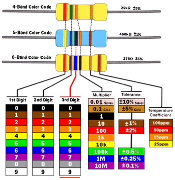
A. 4 bands Resistor:
• The first band gives the first digit.
• The second band gives the second digit.
• The third band indicates the number of zeros.
• The fourth band is used to shows the tolerance (precision) of the resistor.
This resistor has red (2), green (5), orange (3 zeros) and gold bands.
So its value is 25000 = 25 k .± 5%
On circuit diagrams the is usually omitted and the value is written 25K.
B. 5 Band Resistor
- The first band gives the first digit
- The second band gives the second digit
- The third band gives the third digit
- The fourth band is indicates the number of zeros
- The fifth band is used to shows the tolerance (precision) of the resistor

This resistor has yellow (4), blue (6), black (0) orange (3 zeros) and brown bands.
So its value is 460000 = 460 k .± 1%
On circuit diagrams the is usually omitted and the value is written 460K
C. 6 Band Resistor
• The first band gives the first digit
• The second band gives the second digit
• The third band gives the third digit
• The fourth band is indicates the number of zeros
• The fifth band is used to shows the tolerance (precision) of the resistor
• The sixth band is used to shows temperature coefficient

This resistor has red (2), violet (7), blue (6) black (0 zeros/ no zeros) , gold, and brown bands.
So its value is 276 .± 5% , with 100ppm of coefficient temperature
On circuit diagrams the is usually omitted and the value is written 276.
D. SMD Resistor

Surface mounted resistors are printed with numerical values in a code related to that used on axial resistors. Standard-tolerance surface-mount technology (SMT) resistors are marked with a three-digit code, in which the first two digits are the first two significant digits of the value and the third digit is the power of ten (the number of zeroes). For example:
334 = 33 × 104 ohms = 330 kilohms
222 = 22 × 102 ohms = 2.2 kilohms
473 = 47 × 103 ohms = 47 kilohms
105 = 10 × 105 ohms = 1.0 megohm
Resistances less than 100 ohms are written: 100, 220, 470. The final zero represents ten to the power zero, which is 1. For example:
100 = 10 × 100 ohm = 10 ohms
220 = 22 × 100 ohm = 22 ohms
Sometimes these values are marked as 10 or 22 to prevent a mistake.
Resistances less than 10 ohms have 'R' to indicate the position of the decimal point. For example:
4R7 = 4.7 ohms
R300 = 0.30 ohms
0R22 = 0.22 ohms
0R01 = 0.01 ohms
1.4. Resistor in Series
In a series circuit, the current flowing is the same at all points. The circuit diagram shows two resistors connected in series with a 6 V battery:
 Resistors in series
It doesn't matter where in the circuit the current is measured, the result will be the same. The total resistance is given by:

In this circuit, Rtotal=1+1=2 . What will be the current flowing? The formula is:

Substituting:

Notice that the current value is in mA when the resistor value is substituted in .
The same current, 3 mA, flows through each of the two resistors. What is the voltage across R1? The formula is:

Substituting:

What will be the voltage across R2? This will also be 3 V. It is important to point out that the sum of the voltages across the two resistors is equal to the power supply voltage.
1.5. Resistor in Paralel
The next circuit shows two resistors connected in parallel to a 6 V battery:
 Resistors in parallel
Parallel circuits always provide alternative pathways for current flow. The total resistance is calculated from:

This is called the product over sum formula and works for any two resistors in parallel. An alternative formula is:

This formula can be extended to work for more than two resistors in parallel, but lends itself less easily to mental arithmetic. Both formula are correct.
What is the total resistance in this circuit?

The current can be calculated from:

How does this current compare with the current for the series circuit? It's more. This is sensible. Connecting resistors in parallel provides alternative pathways and makes it easier for current to flow. How much current flows through each resistor? Because they have equal values, the current divides, with 6 mA flowing through R1, and 6 mA through R2.
To complete the picture, the voltage across R1 can be calculated as:

This is the same as the power supply voltage. The top end of R1 is connected to the positive terminal of the battery, while the bottom end of R1 is connected to the negative terminal of the battery. With no other components in the way, it follows that the voltage across R1 must be 6 V. What is the voltage across R2? By the same reasoning, this is also 6 V.
KEY POINT : When components are connected in parallel, the voltage across them is the same
2. VARIABLE RESISTOR
2.1. Potentiometer
A potentiometer is a three-terminal resistor with a sliding contact that forms an adjustable voltage divider. If only two terminals are used (one side and the wiper), it acts as a variable resistor or rheostat. Potentiometers are commonly used to control electrical devices such as volume controls on audio equipment. Potentiometers operated by a mechanism can be used as position transducers, for example, in a joystick.
A. Picture

B. Symbol

C. Potentiometer marking
As ussually a potentiometer has value :
- 5KB , it means 5 Kilo ohm with linear function
- 5KA , it means 5 Kilo ohm with logaritmic function
2.2. Trimpot/Trimmer
A. Picture

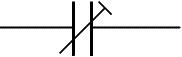
B. Symbol

C. Trimpot Marking
As ussually a trimpot has value
-103, it means 10 x 103 = 10000 = 10 Kilo ohm
-102, it means 10 x 102 = 1000 = 1 Kilo ohm
3. THERMISTOR
A thermistor is a type of resistor whose resistance varies significantly with temperature, more so than in standard resistors. The word is a portmanteau of thermal and resistor. Thermistors are widely used as inrush current limiters, temperature sensors, self-resetting overcurrent protectors, and self-regulating heating elements.
Picture :

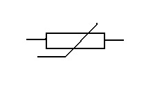
Symbol :

Thermistors can be classified into two types, depending on the sign of k. If k is positive, the resistance increases with increasing temperature, and the device is called a positive temperature coefficient (PTC) thermistor, or posistor. If k is negative, the resistance decreases with increasing temperature, and the device is called a negative temperature coefficient (NTC) thermistor.
4. LIGHT DEPENDENT RESISTOR (LDR)
An LDR is an input transducer (sensor) which converts brightness (light) to resistance. It is made from cadmium sulphide (CdS) and the resistance decreases as the brightness of light falling on the LDR increases.
Picture:
Symbol:
A multimeter can be used to find the resistance in darkness and bright light, these are the typical results for a standard LDR:
• Darkness: maximum resistance, about 1M .
• Very bright light: minimum resistance, about 100 .
For many years the standard LDR has been the ORP12, now the NORPS12, which is about 13mm diameter. Miniature LDRs are also available and their diameter is about 5mm.
An LDR may be connected either way round and no special precautions are required when soldering.
References:
1. “Succes in Electronic” by Tom Duncan
2. Wikipedia.org
3. kpsec.freeuk.com


